|
"The Chance Vought F4U Corsair was a carrier-capable fighter
aircraft that saw service primarily in World War II and the
Korean War. Goodyear-built Corsairs were designated FG and
Brewster-built aircraft F3A. The Corsair served in smaller air
forces until the 1960s, following the longest production run
of any piston-engined fighter in U.S. history (19421952).
Some Japanese pilots regarded it as the most formidable
American fighter of World War II. The U.S. Navy counted an
11:1 kill ratio with the F4U Corsair." -
Wikipedia |
A
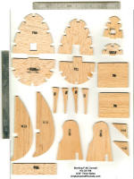
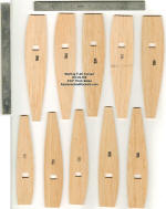
1960s vintage F4U-1 Corsair control line kit from Sterling showed up
on eBay, so I bid on it and got it for just $35 - quite a buy! The
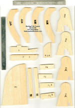
box was faded, but the parts were all there. Die cutting quality was
what could be expected from the era, although having bought a lot of
similar kits back in the day, I can say from experience that the die
cutting was pretty good. Even the plywood parts came out of the
sheets fairly easily. The photo below shows all the parts removed
from their die-cut sheets, along with all the other parts, laid on
top of the plans.
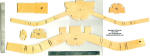
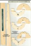
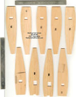
I took the plans to Staples to have a 1:1 copy made to build on so
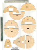
that the originals would not be compromised. I also scanned the
die-cut parts to have a record of the outlines, since the plan do
not include that (see images below).
My intention is to use electric power since it is nice and clean.
Admittedly, it will seem a bit weenie to not have a screaming
internal combustion engine hauling this manly WWII fighter around
the circle, but it's a compromise I'm willing to live with for the
sake of no oily mess and works-every-time motor runs. The
inexpensive, programmable motor sequence timers makes operation a
breeze. |
|
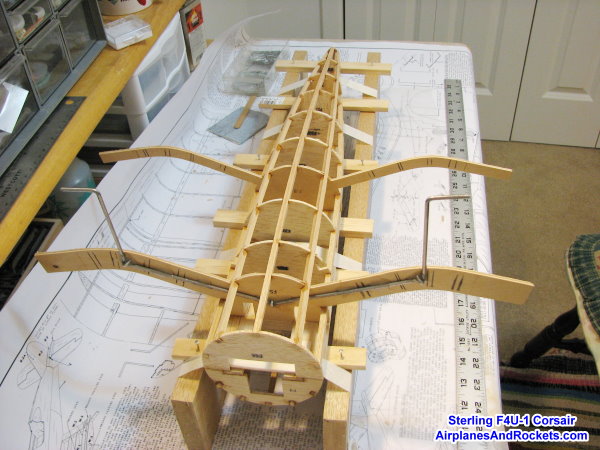
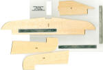
Here is the beginning of the actual construction, after cutting out
all the parts. Instructions on the plans do not indicate that the
top half of the fuselage should be built first while pinned to the
board. Doing so, however, will assure a straight assembly on which
to attach the lower half of the formers. Doing it the way the plans
indicates would make achieving a straight fuselage without conjuring
up some sort of 3-D jig. I will probably use some sort of jig anyway
when assembling the lower former halves, but this way the fuselage
will be a good solid reference to begin with. |
|
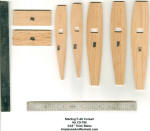
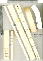
 Here
is the Sterling F4U-1 Corsair fuselage bottom assembly on an
alignment jig that I made from two equal dimensioned pieces of wood,
with thin slats run through the fuselage. It was necessary to tape
the main balsa longerons down to counter the bending force of the
top stringers before the bottom stringers were added. This shot also
shows the landing gear attachment to the plywood former using J
bolts (with a few dabs of epoxy to stabilize it on the former). At
least part of the bottom balsa sheeting will be installed prior to
removing the fuselage from the jig. Here
is the Sterling F4U-1 Corsair fuselage bottom assembly on an
alignment jig that I made from two equal dimensioned pieces of wood,
with thin slats run through the fuselage. It was necessary to tape
the main balsa longerons down to counter the bending force of the
top stringers before the bottom stringers were added. This shot also
shows the landing gear attachment to the plywood former using J
bolts (with a few dabs of epoxy to stabilize it on the former). At
least part of the bottom balsa sheeting will be installed prior to
removing the fuselage from the jig.
It should be a very strong and rigid structure once completed -
which was necessary with the often rough-running engines of the day.
The brushless motor that I am using will not require nearly as much
beef, so I'll probably do a bit of selective lightening throughout
the structure as it progresses.
This appears to be a very well-engineered model. It is too bad that
these kinds of kits are no longer available. The good news is that
some of the folks who sell laser-cut short kits are beginning to
make some nice scale control line models available. They would not
be likely to supply the pre-shaped gull wing leading edges or
tapered balsa parts, so extra carving would be required - not an
insurmountable task to anyone willing to take on building such a
model in the first place.
More to come as the Corsair progresses... The gull wing should be
fun to build!
The AMA Plans Service offers a full-size version of plans at a very
reasonable cost. They will scale the plans any size for you.
http://www.modelaircraft.org/plans.aspx |
 This
article is reproduced from Kirt Blattenberger's website
This
article is reproduced from Kirt Blattenberger's website