SPEED

   
  International Competition Australian Australian Speed Classes  


  US OTS Speed Class Australian Australian  


Claus Maikis artwork


Description Notes


...... Top of Page


F2A


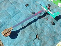
F2A or FAI speed is the premier speed event flown locally and at world championship level. It can be the most expensive and is definitely the most technically demanding of all the speed classes. Purpose built engines and models are the go here, no compromises at this level.

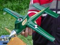
Over recent years models have evolved into single winged, side mounted streamlined speed machines. Nothing is there that isn’t necessary. Wings are made from strong aluminium formed to an airfoil section only a few millimetres thick. The bodies can still be made from wood or more up to date composites such as glass and carbon fibre.

Engines are purpose built with a maximum capacity of 2.5cc. Full length tuned exhaust systems are used to extract maximum power from these speed demons at over 40,000 rpm. World championship speeds are around 300kph.
These things will definitely get your attention, and well worth the trip to our field at Old Wells Road Seaford.


...... Top of Page


F2A - Rules
 
4.1.

CLASS F2A - SPEED MODEL AIRCRAFT

4.1.1.

Definition of a Speed Model Aircraft

Model aircraft in which the power is provided by a piston motor and in which lift is obtained by aerodynamic forces acting on the supporting surfaces, which remain fixed in flight except for control surfaces.

4.1.2 Characteristics of a Speed Model Aircraft
  Maximum swept volume of motor or motors 2.5 cm3
  Minimum total area (St) 2 dm2/cm3 swept volume of the motor(s)
  Maximum loading 100 g/dm2
  Maximum wingspan 100 cm
 

To determine the wingspan of asymmetric model aircraft the thrustline of the model aircraft is used. Refer Sporting Code Volume ABR Section 4C paragraph 1.4.5.

The model aircraft must take off from the ground.

A silencer is compulsory. Minimum internal volume 50 cm3. Maximum tailpipe internal diameter 6 mm.

An effective shutoff is compulsory so that the duration of high level noise can be limited to 20-30 seconds per flight.

Rule B.3.1. of Section 4B does not apply to class F2A.

4.1.3.

Fuel

Fuel to a standard formula for glow plug and spark ignition motors will be supplied by the organisers. Its composition shall be 80% methanol, 20% castor oil.

Note: Fuel for compression ignition motors is not restricted.

Before each attempt for an official flight the fuel tank must be rinsed (washed out) with standard formula fuel.

4.1.4.

Diameter of Control Lines

Only two line control is allowed, minimum control line diameter is 0,40 mm with a tolerance of minus 0.011 mm.

4.1.5.

Length of Course

The measured distance covered by the model aircraft must be at least one kilometre. The radius of the flight circle must be 17.69 m. ( 9 laps = 1 km ).

4.1.6.

Line Tests (to be made before each attempt for an official flight)

The radius is measured from the axis of the pivot on the pylon, to the axis of the propeller. Where two propellers are employed, the axis of symmetry is taken as the reference for measurement.

A load test shall be applied to the assembled control handle, lines and model aircraft equal to 50 times the weight of the model aircraft and this test shall be applied separately to the safety strap when attached to the competitor's wrist.

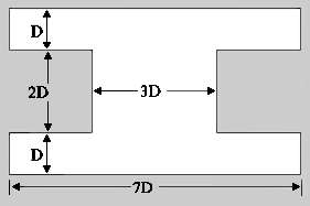
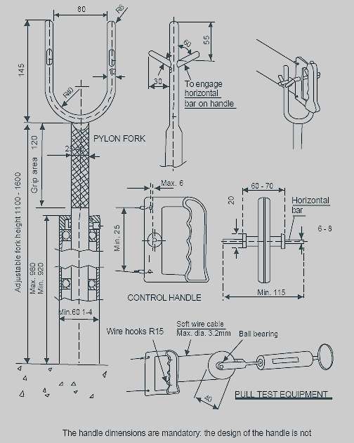
In each case the pull shall be applied three (3) times, slowly increasing to maximum load and releasing rapidly. The pull test should be made on the handle grip, not near the point of attachment of the lines (see sketch ).

The diameter of the lines shall be checked at random distances on at least three points along the length of each line.

4.1.7.

Control Handle and Pylon Fork

A pylon with supports as shown in the sketch, will be placed at the disposal of the competitors by the organisers. It is compulsory that a pylon fork and control handle of standard dimensions as specified, be employed. The distance between the flexible point of attachment on the control handle and the point of contact of the horizontal bar on the fork shall be a maximum of 6 mm. The horizontal bar (handle pivot) must be in continuous contact with the pylon fork during the official flights.

The pylon fork shall be infinitely adjustable between 1100 mm and 1600 mm from the ground and be steadily fixed to the ground surface. Mandatory dimensions are shown in the sketch. The pylon fork in its highest position may not deflect more than 20 mm when it is subjected to a horizontal pull test of250 N.

No intentional twisting and/or linking of the two lines together shall be permitted from the point of exit of the model aircraft to the control handle. The lines shall be separated by at least 5 mm at the point of exit from the model aircraft and at least 25 mm at the handle.

The lines must be round in cross-section and may not have any liquid or coating material applied.

A safety strap connecting the competitor's wrist to the control handle must be provided by the competitor and used during all flights.

4.1.8.

Definition of an Attempt

It is considered an attempt when the pilot does not engage the control handle in the pylon fork within 3 minutes after the starting signal.

4.1.9.

Number of Attempts

In the case of an unsuccessful first attempt for an official flight, the competitor is entitled to a second attempt.

4.1.10 Definition of an Official Flight

The flight is official when the timekeepers start the watches.
4.1.11. Number of Flights

Each competitor is entitled to three official flights.
4.1.12.

Number of Helpers

Two helpers and the team manager are admitted to the contest area. A pilot may start and adjust his own motor and at most one other motor as a helper. Only team members (including the Team Manager) are allowed to start and adjust the motor(s).

In case of an incomplete national speed team supporter(s) may act as helper(s) provided that he (they) is (are) registered as such for no more than one national team from the beginning of the contest through its close, and provided that the team member(s) plus helper(s) do not exceed three persons.

4.1.13.

Starting of Timing

The timing commences officially when the competitor has placed his handle in the pylon fork and the model aircraft having made 2 complete circuits again passes the height marker on the edge of the circuit directly opposite the timekeepers.

4.1.14.

Height of Flight

During the timing of an official flight, the flying height must not be less than one metre and not more than 3 metres.

4.1.15. Cancellation of the Flight

A flight is cancelled when:
  a)

any physical effort for the purpose of increasing the speed of the model aircraft during an official flight is applied by the pilot.

  b)

if at any time during the speed course the model aircraft exceeds a height of 6 metres or sustains a height in excess of 3 metres or less than one metre for more than one lap.

  c) continuous contact is not maintained with the pylon fork during the official flight.
  d) jettisoning occurs during the official flight.
4.1.16 Number of Timekeepers and Judges
  a)

The time shall be taken by either three timing officials equipped with 1/100-second resolution digital stopwatches or by an optical electronic system with equal or better resolution or accuracy. For World and Continental Championships this system must be duplex so that the duplex system serves as the required backup system. For other contests, the required backup for a single system may be by some other electronic device or by two manual timekeepers.

  b)

Speed judges, at least two in number, shall be responsible for observing the conduct of the pilot and the altitude of the flight.

  c)

For World and Continental Championships, a senior judge will be appointed to supervise the conduct of the timekeepers and judges.

The senior judge will be selected from a list of persons who are nominated by NACs for their proficiency and experience and approved by the CIAM.

4.1.17. Classification
  a)

The individual times recorded by each timing official and/or by an optical electronic system shall be recorded in writing and retained by the senior judge or other official.

  b) Times recorded should be handled as follows:
    i)

In the case of manual timekeepers, the mean time of the three stopwatches shall be taken to calculate the result, unless:

a) One of the stopwatch times differs from the closer of the other two by more than 12/100 seconds, or the official reports that he made a mistake. In this case the mean time shall be calculated from the other two stopwatch times.

b) Two stopwatch times differ by more than 12/100 seconds from the middle one, or two officials report a mistake. In this case this fact should immediately be reported to the competitor or his team manager. The competitor then has the choice of using only the remaining stopwatch time to calculate his result, or to be allowed an attempt. His decision must be given to the F2A Circle Marshall without delay, and is irrevocable.

c) No rounding off of decimals should be made when calculating the mean time. The time thus obtained for calculating the speed should be recorded and retained.

    ii)

In the case of an optical electronic system, the senior speed judge should check the result by looking at the logged individual lap times of the official flight, as well as the laps before and after the official flight. If there is any anomaly, the backup system should be consulted. If the backup system is manual and both timekeepers report a mistake (they may have timed one lap short), the competitor should be given a replacement attempt. If the backup time, either manual or secondary electronic, is within 12/100 of the primary system time, the primary system time is used. If the backup time, either manual or secondary electronic, differs by more, but is in itself consistent, its time should be used. If an uncertainty in excess of 12/100 seconds remains, then the competitor has the choice of choosing the slowest recorded speed or being allowed a replacement attempt. His decision must be given to the Circle Marshal without delay, and is irrevocable.

  c)

The result of the speed in km/h shall be calculated by dividing 3600 by the time according to b), and then taken to the nearest lower 1/10 km/h.

  d)

The best speed attained during the three flights is used for classification. In case of a tie, to separate the fliers, the second best speed, and if still a tie, the third best speed is used.

  e) The three first positions are subject to rechecking of the declared model aircraft characteristics.
4.1.18.

International team classification

To establish the national team scores for the team classification, add together the best speed attained by each individual member of the team. In a case of a team tie, the team with the lower sum of place numbers, given in order from the top, wins. If still equal, the best individual placing decides.


Text and images are from the
FAI SPORTING CODE, SECTION 4C, PART FOUR
2006 Edition - Effective January 1, 2006


...... Top of Page


PROTO SPEED


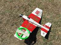
Proto Speed is an event for those who want to try a speed event. Models must conform to the model size, engine size and relevant minimum line size specifications for the Class II team racer. They must have fixed undercarriage and be flown on dual control lines of minimum length 18.3 metres. Single strand lines are recommended. How ever, multi-strand lines may be used. Fuel and tanks are unrestricted.

The model bellcrank, lines and handle shall be subject to a 35g pull test. The maximum flying height is five metres. The event is timed as a drag race of 1.6 km [14 laps] and for flight to be official a pylon must be used within 3 laps. A pylon must be used by the end of the first lap when a record is being attempted.


...... Top of Page


PROTO SPEED - Rules
 

Refer to the Categories / Racing section for Class II Team Race


...... Top of Page


AUST SPEED CLASSES


Description Notes


...... Top of Page


AUST SPEED CLASSES - Rules

4.3

CONTROL LINE SPEED CLASSES

4.3.1 Model Characteristics
  a) No restrictions on areas or loadings.
  b) Model may R.O.G. or be hand-launched, except for Jets which will be R.O.G. only
  c) Detachable undercarriages are permissible for R.O.G.
  d) For Class V: Models to be upright engine design with a wing not more than 1 inch difference between inboard or outboard wings. Single blade propellers not allowed.
4.3.2 Fuel Fuel is unrestricted, but see 2.4 [e].
  a) Sport Jet :- Allowable fuel to be a minimum of 80%; Shellite, White spirit, petrol or methanol, with no more than 20% additive of Propylene oxide, Nitro methane, MEK or similar. Open Jet fuel is unrestricted.
4.3.3 Classes and Specifications
 
  Class I Class II Class III Class IV Provisional Class
Class V
Open Jet Provisional Class
Stock Jet
Max. Engine Capacity 2.2cc 5.0 cc 10 cc 6.6 cc
(5.01cc min.)
3.5cc See #A below See #B below
Min. flight radius 15.92 m 18.3 m 21.35 m 19.8 m 17.69 m 21.35 m 18.3 m
Min. line dia.
Dual lines
.30 mm 0.455 mm 0.60 mm 0.50 mm 0.455 mm 0.60 mm 0.525 mm
Mono line N/A 0.60 mm 0.787 mm 0.787 mm N/A 0.787 mm N/A
Max. Weight 500 gm 950 gm 1300 gm 1000 gm 800 gm 1300 gm(wet) 1300 gm(wet)
  #A Max. Engine Capacity for JET
    80mm Maximum combustion chamber.
9.675 cm2 maximum internal cross section of tailpipe
  #B Max Engine Capacity for Jet (Stock)
    65 mm Maximum head length (valve face to air intake)
  Note: The metric dimensions shown have been converted from imperial measurements.
Equivalents are:-
   
0.300 mm = 0.012 in   15.92 m = 52 ft 3 in
0.406 mm = 0.016 in   17.69 m = 58 ft 5 in
0.455 mm = 0.018 in   18.30 m = 60 ft
0.500 mm = 0.020 in   19.80 m = 64 ft 11.5 in
0.525 mm = 0.021 in   21.35 m = 70 ft
0.560 mm = 0.022 in        
0.600 mm = 0.024 in        
0.787 mm = 0.031 in        
 

For Class I: Divergent cone exhausts are forbidden. Open exhaust or non divergent constant diameter exhaust extensions may be used.

For Class IV: Divergent cone exhausts are forbidden. Constant diameter type extensions are allowed, provided that the overall length (measured from the centre-line of the piston to the end of the exhaust system) does not exceed 150mm. The measurement shall be along the centre line of the exhaust system.

For Class V: Divergent cone exhausts are forbidden. Constant diameter type extensions are allowed, provided that the overall length (measured from the centre-line of the piston to the end of the exhaust system) does not exceed 150mm.

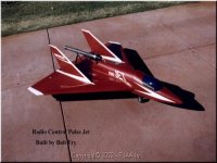
For Jet: Engines to be used in Jet are to be either, O.S., Dyna, Bailey, Home-built or any commercially available jet to the above specifications. The pulse jet is to be attached to the model and is not to be an integral part of the airframe.

4.3.4 a)

Lines are to be of good quality, high tensile, unplated steel and/or steel alloys. Commercially graded wire diameters will be acceptable provided that they do not measure more than 0.0004 in. under nominal size. Multi stranded type lines may not be used.

  b)

All control lines on class 2 and class 3 models are to be attached at the model by the use of bobbins, as is standard practice in mono line classes. Bobbins are to be of steel or material of equal strength. Bobbins are to measure a minimum of the following formula based on the control line wire diameter [D] applicable to the class. The width of the bobbin groove is to be no less than the total of the wire diameters or greater than 0.010 in. clearance on the wire diameters. [See diagram, page 2 - 44]

  c) All handle connections are to have a deformation strength greater than the control line used.
  d)

Where the two-line configuration is used on any class of speed model, no twisting or linking together of the two lines is permitted.

  e)

A safety strap or similar device effectively connecting the pilot and the handle together must be used.

  f)

Class I, Class IV and Jet models using dual lines must use bobbins to the above formula. Double over locking type connectors or similar with a minimum strength of 20 kg [ 44 lbs] for Class I and 45 kg (100 lbs) for Jet and Class IV may be used with bobbins. The use of line connectors only is not permissible and centre type connectors are banned.


4.3.5 Line Length Measurement (Flight Radius)
 

Lines shall be measured from the grip edge of the handle grip - finger grip if torpedo type handle is used, or cross bar (if fitted to the handle) - to the axis of the propeller. Where two or more engines or propellers are employed, the axis of symmetry is taken as the reference for measurement.

4.3.6 Line Tests Line tests shall be made prior to each flight.
  a)

The entire system of safety strap, handle, lines and model shall be subjected to a pull test of 40g for Class I, 45g for Class II, Class IV and Jet, and 50g for Class III.

  b) In addition to the load test, a visual examination is to be made by the Contest Director, FAI Observer or other appointed officer.
  c) The Contest Director or other authorised person responsible for checking lines and equipment has the right to disallow any model, on points of safety, even if the requirements of the rules are fulfilled.
4.3.7 Length of Courses
  All classes, except Class I and IV which will be flown over 1000 m (1 km.), will be flown over a measured 804.67 meters [half mile] course comprising the following:-
 
Class I Class II Class III Class IV Class V Open Jet Stock Jet
10 laps 7 laps 6 laps 8 laps 9 Laps 6 laps 7 laps
4.3.8 Number of Timekeepers and Judges
  a) For an attempt to be recognised as an official flight, there must be present three [3] timekeepers who are known to be experienced and capable, each equipped with a 1/100th second stopwatch. In addition an optical electronic system with equal or better resolution and accuracy may be used.
  b) An FAI Observer must be present as witness to the timekeepers, or be one of the timekeepers, and is to ensure that all aspects of the flight, timekeeping and processing of the model conform to the rules.
4.3.9 Starting of Timing
  For timing to commence, the pilot must position the control handle in the pylon fork so that the point on the handle from which the line length was measured is not behind the pylon pivot.
4.3.10 Timing Procedure
  a) Upon the pilot placing the handle correctly in the pylon fork, the timekeepers shall allow two full laps from opposite the timekeeping position before starting timing for the appropriate number of laps.
  b) The time keepers , in unison, will count down and then up throughout the flight - that is, , 2-1-0-1-2-3-4-5-6-7-8-9 or 10.
  c) The official time shall be the average of the three watches, if all the watches are within 1/10th of a second. If only two watches are within 1/10th of a second, then the average of the two will count; the third watch will be ignored.
  d) In the event that none of the watches are within 1/10th of a second of each other, then the competitor may claim the longest time or request a repeat of his flight.
4.3.11 Cancellation of the Flight A flight is cancelled:-
  a) when any form of assistance is applied for the purpose of increasing the speed of the model, other than that provided by the engine, during the official part of the flight;
  b) if, at any time during the timing procedure, the model exceeds a height of 4.5 metres [15 feet] for more than one lap;
  c) continuous contact is not maintained with the pylon fork during the timing procedure; or
  d) jettisoning of other than the take off dolly occurs.
4.3.12 Number of Flights and Attempts
  a) Each competitor is entitled to three official flights.
  b) Two attempts shall constitute an official flight.
  c) An attempt shall not be more than three minutes, or five minutes for Jet.
  d) A competitor may elect to call an attempt and use the pylon provided the Contest Director is notified beforehand.
  e) The flight is official whenever the competitor places his handle in the pylon fork during an attempt and when the timekeepers start the watches, except under rule 4.3.12.d].
4.3.13 All participants must be current affiliate members of the MAAA(Inc).
4.3.14 Records may be set at sanctioned contests without prior notice and at such times and places as outlined by Section 7 of Chapter 2 of the Rules Handbook.
4.3.15 All other record flights must be witnessed by an FAI Observer who shall ensure that all requirements of the rules are met.
4.3.16 Contest organisers may run the event combining all speed classes and award places on the achieved percentage of current speed records in the class contested. When there is a minimum of five entries in Jet Speed, it may be run concurrently with Combined speed although listed as a separate event.

A contestant can fly all classes and place more than once if the event is organised in this fashion.
 

Text and images are from the
Australian Rules, Section 3,
2006 Edition - Effective January 1, 2006

...... Top of Page


PERKY SPEED


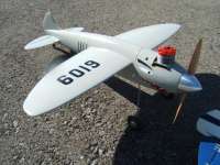
This is a one design contest using the Megow PERKY designed by Matt Kania. The Perky was kitted by Megow of Philadelphia Pennsylvania in 1947 and was a control line Class A speed plane with a span of 18" and 64 sq. in area designed for .19 size ignition engines.


...... Top of Page


PERKY SPEED - Rules
 

NASS Perky OTS Speed Rules
November 6, 2007
Reviewed and approved by NASS Technical Director to ensure compliance with AMA Safety rules.
This is a one design speed event.
The Model is the 1946 Matt Kania designed Megow Perky. The rules are pretty basic.

  1. The Model must be built to the out line of the original 1946 Megow Perky design. Construction modifications allowed.
  2. Model must be equipped with a 1 ½” or 1 Ύ” Spinner.
  3. Model must be equipped with two wheels of 1 3/8” to 1 ½” Diameter.
  4. Only Suction type Fuel Systems are allowed. No Pressure Systems.
  5. The Engine size shall be .15 cu in Glow or Diesel. Or .19 cu in Ignition engine.
  6. Glow Engines are to use the AMA 10% Spec Control Line Speed Fuel. No fuel restrictions for Diesel or Ignition Engines.
  7. No Tuned Pipes or Megaphone exhaust extensions allowed. Mini Pipes and Mufflers are ok.
  8. Maximum Model weight shall be 23 oz.
  9. The flying wires shall be 52’6’’ in length as measured from the centre line of the fuselage to the centre of the grip on the control handle. Only 2 wire control systems allowed.
10. The flying wires shall be .014” Diameter Solid Steel Music wire. Wire material shall be the AMA required ASTM A228M Spec wire.
11. A Pull Test of 25g’s shall be applies to the model, flying wires, handle and safety thong prior to each attempt.
12. The Model will be timed for 1 mile, 16 Laps from the point of release.
13. The Pilot is not required to use the AMA Speed Pylon.
14. A Contestant may enter more than one model. This would require an additional entry fee to be collected.
15. For each model entered, the Contestant will be given 4 attempts to complete 3 official flights.
16. All other safety rules in the AMA Rule book apply.
  There will be one award for the Model closest to the Average Speed of all Models, and awards for Top Speed, 1st through 3rd place.
 

...... Top of Page


MIDGE SPEED


Description Notes


...... Top of Page


MIDGE SPEED - Rules
 
14.

Midge Speed

14.1. General
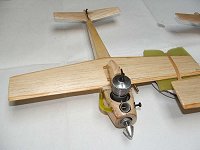
  Midge speed is a one design event based on the simple to build Midge design. This is a suitable introduction to speed flying using easy to fly, low cost equipment.
14.2. Speed Site
  The speed circle shall preferentially be marked out on grass. Use of a pylon is preferred if available.
14.3. Characteristics of a Midge Speed Model
  14.3.1. Maximum Engine Capacity: 1.6cc
  14.3.2. Engine Type: Any plain bearing non schnuerle ported diesel engine may be used. (eg PAW 3 port, Silver Swallow Cipolla Junior, Taipan PB etc)
  14.3.3. Model Design:
    14.3.3.1. The model must conform to the original "Mercury Midge" plan or the CLAS "Basic Midge".
    14.3.3.2. Dimensions shown on the plan are for construction purposes only and will not be used for model processing.
    14.3.3.3. The fuselage may be widened to suit the engine used.
  14.3.4. Fuel System: A suction feed fuel system shall be used.
  14.3.5. Fuel: The fuel is unrestricted.
14.4. Control Systems
  14.4.1. Line Length: The length of the control lines must be 10.66m. The length is measured from the face of the handle grip to the centre line of the model.
  14.4.2. Control lines: Two multi-strand control line wires of a minimum diameter of 0.3mm shall be used. No intentional twisting or linking of the lines is allowed.
  14.4.3. Line Tests: A pull test of 20g shall be applied to the model/line/handle combination.
14.5. Contest Procedure
  14.5.1. Attempts: Each contestant shall be allowed two (2) attempts per round to record an official flight. It will be considered an attempt when the pilot does not signal, or does not engage the control handle in the pylon within 3 minutes after the starting signal.
  14.5.2. Official Flight: A flight is official whenever the competitor places his handle in the pylon or signals if no pylon is available.
  14.5.3. Number of Flights: Each competitor is entitled to three (3) official flights.
  14.5.4. Timing: Timing will commence two (2) laps after the handle is placed in the pylon (or the pilot signals if no pylon), and will continue for six (6) laps.
  14.5.5. Flying Height: Flying height shall be between 1 and 3 metres during the official flight.
  14.5.6. Whipping: Use of physical effort to increase the model's speed will result in disqualification.
  14.5.7. Best Time: The competitors best time for 6 laps from 3 official flights shall be used for calculating the contest results.
14.6. Contest Results
  14.6.1. Placings: Midge Speed will normally be flown in conjunction with Australian Combined speed. The competitors result will be calculated as a percentage of the current Australian record in Midge Speed.
 

...... Top of Page